 Basic Measurements
  Basic Measurements
 All measurements in the SensorPlot™ application are represented by mathematical equations called traces. The system automatically creates pre-defined measurements (equations) of position, velocity, acceleration and analog voltage for all encoder and analog inputs. These pre-defined measurements, called measurables, act like vector variables that are filled with samples as the system acquires data. Particular measurables are distinguished by a suffix attached to the end of the encoder or analog channel name (the name assigned during configuration). Each encoder channel of a Motion Capture card supports six measurables. The list below represents the measurables corresponding to an encoder input named EncoderName.
| EncoderName.pos | Measurement of standard position |
| EncoderName.vel | Measurement of standard velocity |
| EncoderName.acc | Measurement of standard acceleration |
| EncoderName.StrbPos | Measurement of strobed position |
| EncoderName.StrbVel | Measurement of strobed velocity |
| EncoderName.StrbAcc | Measurement of strobed acceleration |
Measuring Position
Basics of measuring position using counters:
| Encoders, photo-interrupters and other motion sensors generate a pulse in response to a known incremental move in position. The position of an object can be continually measured by connecting the output of an encoder (or other sensor) to a counter that increments or decrements every time the sensor generates a pulse. The value of the counter indicates the position of the object quantized to the resolution of the sensor. That is, if a sensor generates 10 pulses per revolution, the resolution of the position measurement can be no better than 1/10th of a revolution. |
The Motion Capture cards use the method above as well as an adaptation of the counter method described above to provide two methods to measure position.

Strobed Position:
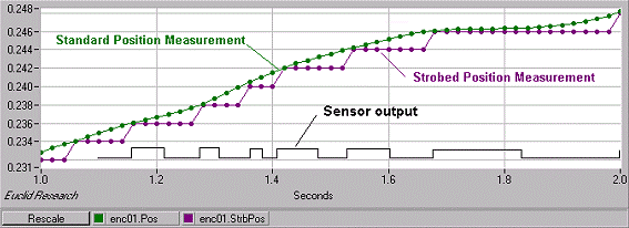
Strobed position, indicated by EncoderName.strbpos, measures the position of an object by capturing (strobing) the value of the position counter every time a sample is requested by the Timebase. Because the position counter connected to the encoder only increments whenever the sensor generates a pulse, all strobed measurements are quantized to +/- ½ count. That is, in a sequence of strobed measurements, each successive measurement will be equal to the previous measurement or equal to an integer multiple counts of the counter (see the graph above comparing strobed and standard position measurements).
Standard Position:
In contrast to the strobed position measurable that simply captures position counter values, the standard position measurable, identified by EncoderName.pos, computes values that predict what the positions would have been at the time of each sample. This measurable more accurately describes the position of an object as measured by the encoder. As illustrated by the graph above, the standard position measurable interpolates position to the sample times between the encoder pulse locations. Subsequently, the standard position measurable doesn't suffer from discontinuities around the sensor pulse times.
Incremental Vs Absolute Position:
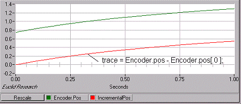
 The Motion Capture card continually tracks the position (counts the pulses) of an encoder or other sensor even when the SensorPlot™ application isn't acquiring data. Over a period of time, the position values associated with an encoder channel can become quite large. To force the position values to start from zero at the beginning of every acquisition, the index operator, [ ], can be applied to offset the vector of position values by the first position measurement. To the right is an example position measurement trace that when plotted always starts from zero at the beginning of an acquisition:
trace = Encoder.pos - Encoder.pos[0]
Identifying a Single Revolution of an Object:
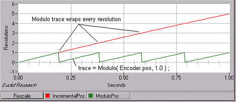
Another function that can be applied to the measurement of position is the modulo function. The modulo function allows you to constrain a measurement to a particular range of values by folding and overlaying values that are outside a specified range. Illustrated below, the position measurement trace IncrementalPos, shows the encoder making 5 revolutions in one second. The trace constructed using the modulo function, ModuloPos, creates a vector of measurements that wrap to zero whenever the position values exceed the value of 1 (1 being specified as the point where the modulo function should wrap).

Traces like the example trace ModuloPos shown above come in handy when you want to plot something versus position. To create a "something" versus "position" graph you simply set the X axis of the graph to use the trace containing the modulo function.

Resetting the Encoder Position Counters:
To reset the position counters of one or more encoders you can use the Reset Encoder Chans button inside the Calibration panel of SensorPlot™. The reset encoder mechanism sets the position counter of an encoder channel to zero at the instant the button is pressed. Forcing the position counter to zero allows you to start an acquisition with small position values (zero if the acquisition is started before the encoder moves).
Forcing the position counter to zero also allows you to calibrate the position of the encoder relative to some external marker. For example, if the encoder is aligned with an external marker and the Reset Encoder Chans button is pressed, then you can be assured that whenever the encoder takes on a position value of zero (or a multiple of the encoder's PPR) it is aligned with the marker.
It should be noted that all encoder channels are reset simultaneously whenever the Reset Encoder Chans button is pressed. Therefore multiple encoder channels are guaranteed to take on zero values simultaneously even when some are connected to active (moving) encoders.
Measuring Velocity and Acceleration
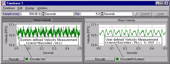
Like the measurement of position, SensorPlot™ supports predefined measurements of velocity and acceleration. These measurements are internally computed by taking the derivative of position with respect to time. The aperture passed to these measurables controls the 'dt' component of the derivative, d(position)/dt. These measurables also exist in an optional form that requires no aperture. The no aperture form uses the time between adjacent samples as the 'dt' component of the derivative. As illustrated below, the aperture allows you filter out any high frequency dynamics that are amplified when you take their derivative.

Computing Velocity and Acceleration Using the Derivative function:
Included in the list of mathematical functions available to traces is the diff() function. The diff() function computes the derivative with respect to time over a given time interval (aperture). Below are the equivalent trace equations for the velocity and acceleration measurables automatically created by the system:
| EncoderName.vel | trace=diff( EncoderName.pos, 200.0e-6 ); | |
| EncoderName.acc | trace= diff( diff(EncoderName.pos, 200.0e-6 ) ); |
Because velocity and acceleration are simply computed using the derivative (and double derivative) of position, you can use either the measurables themselves or the diff() function to create velocity and acceleration measurements.
Tracking filters:
The diff() function does have one advantage over the standard velocity and acceleration measurables. Unlike the standard velocity and acceleration measurables which take a fixed value for the aperture, the diff() function can accommodate variable time apertures. For example, the ripple on a velocity measurement is sometimes attributable to a phenomenon that is periodic in one revolution of the object being measured. Since the time to make one revolution varies with the speed of the object, a fixed time aperture will not succeed in removing the ripple. Instead, you must apply an aperture whose time value corresponds to the time it takes to make one revolution. Such a computation might look like:
| trace=diff( EncoderName.pos ); | Non-tracking derivative | |
| trace=diff( EncoderName.pos, 1.0, EncoderName.pos ); | Tracking derivative |
The combination 1.0, encoderName.pos indicates to the diff() function that the aperture in time should always equal 1.0 revolution of shaft.pos (regardless of the speed of the shaft).
Euclid Research · 2 North 1st Street, 6th Floor · San Jose, CA 95113-1201
Tel: (408) 283-9020 · Fax: (408) 283-9029