 | SensorPlot Applied to Printer Development and Design |
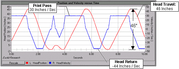
In this example, SensorPlot™ was used to monitor the position and velocity of a print head assembly on a large ink jet printer. Motion was sensed by connecting SensorPlot™ to the linear encoder used to control the printing. Accelerometers attached to the print head were also sampled to assist in diagnosing a periodic anomaly that occasionally appeared in the printed output. The data below corresponds to the motion of a test pattern while SensorPlot™ made measurements every 200uS for 10 seconds.

In the left graph below, velocity is plotted versus head position for easier visualization of the velocity profile. As illustrated, the print head quickly reaches 30 Inches/Sec in about 2.5 inches. The graph on the right presents a zoomed view the velocity of the print head during a print pass. The head appears to be fluctuating back and forth at 352 Hz as it is moved across the paper.

The periodic ripples seen in the velocity measurement are also conveyed in the accelerometer measurements shown below. An additional resonance at 305 Hz is also present in the vertical direction as illustrated by the graph on the right.

Euclid Research · 2 North 1st Street, 6th Floor · San Jose, CA 95113-1201
Tel: (408) 283-9020 · Fax: (408) 283-9029